Difference between revisions of "Structure Map"
(→Structure Properties) |
|||
| (6 intermediate revisions by 2 users not shown) | |||
| Line 1: | Line 1: | ||
| − | [[Category:SDMX Structures]] | + | [[Category:SDMX 3.0 Structures]] |
| + | [[Category:SDMX 3.0 Mapping Structures]] | ||
| + | |||
= Overview = | = Overview = | ||
[[File:StructureMapModel.jpg|thumb|Simple example of a structure map]] | [[File:StructureMapModel.jpg|thumb|Simple example of a structure map]] | ||
| Line 9: | Line 11: | ||
|- | |- | ||
! scope=row style="text-align: left;" | Maintainable | ! scope=row style="text-align: left;" | Maintainable | ||
| − | | [[Maintainable|Yes]] | + | | [[Maintainable V11|Yes]] |
|- | |- | ||
! scope=row style="text-align: left;" | Identifiable | ! scope=row style="text-align: left;" | Identifiable | ||
| − | | [[Identifiable|Yes]] | + | | [[Identifiable V11|Yes]] |
|- | |- | ||
! scope=row style="text-align: left;" | Item Scheme | ! scope=row style="text-align: left;" | Item Scheme | ||
| − | | No | + | | [[Item_Scheme V11|No]] |
|- | |- | ||
! scope=row style="text-align: left;" | SDMX Information Model Versions | ! scope=row style="text-align: left;" | SDMX Information Model Versions | ||
| Line 23: | Line 25: | ||
| StructureMap | | StructureMap | ||
|} | |} | ||
| + | |||
| + | ==Context within the SDMX 3.0 Information Model== | ||
| + | |||
| + | [[File:SDMX3 StructureMap.png|Structure Map|600px]] | ||
==Usage== | ==Usage== | ||
Latest revision as of 07:34, 17 April 2024
Contents
Overview
Structure Properties
| Structure Type | Standard SDMX Structural Metadata Artefact |
|---|---|
| Maintainable | Yes |
| Identifiable | Yes |
| Item Scheme | No |
| SDMX Information Model Versions | 3.0 |
| Concept ID | StructureMap |
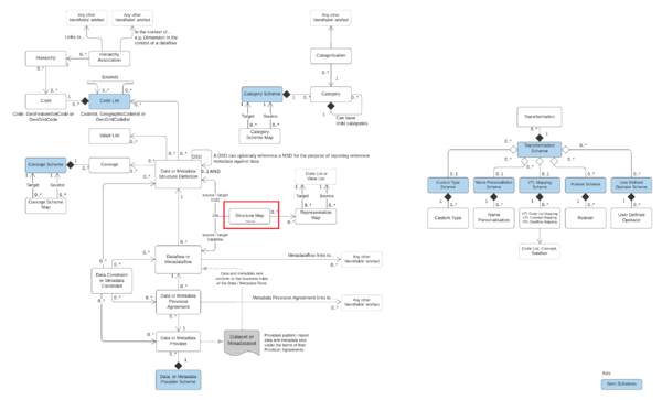
Context within the SDMX 3.0 Information Model
Usage
SDMX Version 3.0 Structure Mapping provides the ability to define a relationship between datasets conforming to a source DSD, to datasets which conform to a target DSD. This relationship allows for the automatic conversion of data from one structure to another. For example a source dataset may contain 8 Dimensions and use certain coding schemes, which may map to a dataset with only 5 Dimensions using different coding schemes.
Structure Mapping does not create new data, it should not be thought of as a mechanism to aggregate data, only to re-organise and re-code it.
Two Maintainable Structures are required to defining how two datasets relate to each other, one is the SDMX Structure Map which is used to define how Components from the source DSD relate to Components on the target DSD, and the other is the Representation Map which is used to describe how values reported for source Components should be converted to conform to the desired output DSD.
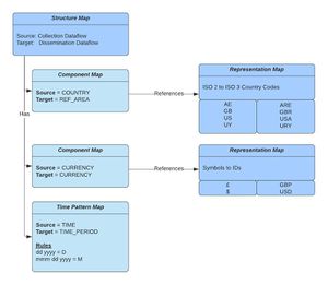
A simple example is a relationship between the source COUNTRY component to the target REF_AREA component. The Structure Map has a source COUNTRY and target REF_AREA, the rules used to define how the values are mapped are maintained in the corresponding Representation Map, an example rule would be GB maps to GBR, US maps to USA, and UY maps to URY.
Structure Map - Model
Source and Target DSD / Dataflow
The Structure Map defines the source and target DSD or if the mapping is Dataflow specific, the source and target Dataflow. The source DSD/Dataflow is the one from which the data will be input into the mapping. Whilst the mapping rules are bi-directional (data mapped one way can be mapped back again) for more complex mappings, which include regular expression matches or substring matches on the source, it is not always possible to map back again. Therefore the source DSD or Dataflow should be selected based on where the data is coming from, and the target is where the data is going to as a result of the mapping.
Component Maps
The Structure Map defines 1 or more Component Maps, each Component Map has 1 or more Components from the source DSD, mapping to 1 or more Components in the target DSD.
1 to 1 Mapping
The most simple relationship is 1:1 mapping, an example being REF_AREA maps to COUNTRY.
1 to n Mapping
More complex relationships allow for the combination of reported values across multiple source components to influence what is output in the target, for example REF_AREA in combination with CURRENCY maps to CURRENCY_DENOM.
n to 1 Mapping
Component Maps may define single source mapping to multiple targets, for example REF_AREA maps to CURRENCY and CURRENCY_DEMOM.
n to n Mapping
Finally multiple sources may map to multiple targets. A full description of how mapping relationships are used to solve use cases is provided in the mapping relationships section.
Defining how values map
Each Component Map can link to a Representation Map, which is used to describe how the source values map to the target values. The linked Representation Map links to source and target Codelists, Valuelists, or Free text. Like the Component Map, the Representation Map may contain multiple sources and multiple targets. The number and order of sources and targets to a Representation Map must match exactly that of the Component Map. For example if a Component Map has 2 sources REF_AREA and CURRENCY, then the linked Representation map must also have 2 sources, one for the REF_AREA Codelist and the other for the CURRENCY Codelist.
Representation Maps can include complex rules, such as regular expressions on source values, and can even define periods of time for which a mapping relationship is true, for example if a relationship between source country and target currency is defined then one could map France to the French Franc up until 2002 and then map France to the Euro from 2002 onwards.
If a values do not require mapping, for example if source FREQ maps to target FREQ and the values are the same in both the source and target DSD, then the Component Map should not link to a Representation Map. The lack of link will inform the system that the value should be copied across verbatim.
Time Mapping
A Structure Map may also define relationships between a source Component and target Component where the value in the source is a representation of time, which needs to be converted to conform to SDMX Time Formatting.
The output of a time mapping is always a date in SDMX format. The date must be mapped to a specific Frequency formatting, this is either defined as a fixed value, or can be linked to the value in another Dimension. For example output Frequency=value reported in FREQ Dimension (in the target DSD).
Time mapping is split into two separate types, Epoch Mapping and Time Pattern Mapping.
Epoch Mapping
This is used if the source Component represents time as a number, the number represents the number of epochs since a base period, and each epoch is a fixed interval of time. An example is UNIX time which is the number of milliseconds since 1970. When defining this mapping, the source Component requires the base period (e.g. 1970), the epoch interval (milliseconds) and the output Frequency (fixed value or based on another dimension value).
Time Pattern Mapping
This is used if the source Component represents time as a string which conforms to a particular pattern, for example mm-dd-yyy (month, day, year). Each pattern can be mapped to a specific frequency, or the general rule of outputting according to a Frequency Dimension can be used.
The following patterns are supported:
| Letter | Date or Time Component | Presentation | Examples
|
|---|---|---|---|
| G | Era designator | Text | AD |
| y | Year | Year | 1996; 96 |
| Y | Week year | Year | 2009; 09 |
| M | Month in year | Month | July; Jul; 07 |
| w | Week in year | Number | 27 |
| W | Week in month | Number | 2 |
| D | Day in year | Number | 189 |
| d | Day in month | Number | 10 |
| F | Day of week in month | Number | 2 |
| E | Day name in week | Text | Tuesday; Tue |
| u | Day number of week (1 = Monday, ..., 7 = Sunday) | Number | 1 |
| a | Am/pm marker | Text | PM |
| H | Hour in day (0-23) | Number | 0 |
| k | Hour in day (1-24) | Number | 24 |
| K | Hour in am/pm (0-11) | Number | 0 |
| h | Hour in am/pm (1-12) | Number | 12 |
| m | Minute in hour | Number | 30 |
| s | Second in minute | Number | 55 |
| S | Millisecond | Number | 978 |
| z | Time zone | General time zone | Pacific Standard Time; PST; GMT-08:00 |
| Z | Time zone | RFC 822 time zone | -0800 |
| X | Time zone | ISO 8601 time zone | -08; -0800; -08:00 |
Components with Fixed Values
Some Components on the output may have a fixed value, for example Frequency is always M regardless of the input data. This is defined at the level of the structure map. As mappings can be bi-directional the input can also have a fixed value, so when mapping the other way (from target to source) the input becomes the output.
Mapping Rules: Use Cases
Many Outputs from a Single Source
An example use case is a Dimension with ID UNIQUE_KEY whose values are used to uniquely define a series, example SER1, SER2, SER3. The mapped DSD splits this into multiple Dimensions FREQ, REF_AREA, INDICATOR. The mapping rules split the unique key SER1 into FREQ:M, REF_AREA:UK and INDICATOR:EMPLOYED. Another unique key would map to a different breakdown of values, for example SER2 maps to FREQ:M, REF_AREA:FR and INDICATOR:EMPLOYED.
Solution 1
This type of use case can be solved by creating 3 Component Maps:
Component Map 1: Source=UNIQUE_KEY Target=FREQ
Component Map 2: Source=UNIQUE_KEY Target=REF_AREA
Component Map 3: Source=UNIQUE_KEY Target=INDICATOR
Each Component Map is backed by a Representation Map, which maps the value of the Unique Key to the output.
Representation Map = UNIQUE_KEY -> FREQ
Values: SER1=M, SER2=M, SER3=A
Representation Map = UNIQUE_KEY -> REF_AREA
Values: SER1=UK, SER2=FR, SER3=UK
Representation Map = UNIQUE_KEY -> INDICATOR
Values: SER1=EMPLOYED, SER2=EMPLOYED, SER3=EMPLOYED
In this example, the unique Key SER1 would be mapped to M, UK, EMPLOYED.
Solution 2
An alternative solution to this mapping is to create a single Component Map which maps the source UNIQUE_KEY to three outputs FREQ, REF_AREA, INDICATOR.
A Single Representation Map is required to map each UNIQUE KEY to the three outputs.
Representation Map = UNIQUE_KEY -> FREQ:REF_AREA:INDICATOR
Values: SER1=M:UK:EMPLOYED, SER2=M:FR:EMPLOYED
Summary
The choice of whether to split the mapping up into separate components vs a single rule should be based on what will be more maintainable, understandable, and can individual mapping rules be reused by other structure maps.
Many Sources map to a Single output
This is the reverse of the above use case, and has the same 2 solutions, split the rules into individual maps, or describe the relationship in a single map. If the rule is split into individual maps, then it is important to note how Fusion Registry determines the final output.
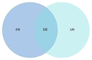
If the output from Component Map 1 is a set of possible value: FR, DE and the output from Component Map 2 is another set of possible values, DE and UK, then the intersection of both sets are used to find the final output, in this case DE.
If-Then-Else (default if not specified)
The order of rules in a Representation Map can be important, specifically when using regular expressions. The regular expressions are tested in the same order that the appear they are defined, this allows for more specific expressions to be tested before a general catch all.
Example
Rule 1 (no regex): A -> B (A maps to B)
Rule 2 (reg ex): A\dB -> B2 (A followed by a number followed by B maps to B2)
Rule 3 (reg ex): .* -> _Z (anything maps to _Z)
Source data will first be checked against the exact match rule (A maps to B), followed by each regular expression rule until a match is found. As the last expression matched on anything, this can be considered as 'if nothing matches then output _Z'.
Pattern match input, use matched text on output
A rule can be defined to match a specific pattern, which is then used in the output. For example the rule can state any three characters followed by a number is converted to the same three characters without the number. This can be satisfied by using Regular Expressions to match the input, with a capture group. A capture group is where the regular expression rule is in parentheses which can then be referred to by number (capture group 1, 2, 3, and so on).
Example:
RegEx Input: ([A-Z]{3})_([0-9])
Output Expression: \2_\1
This example consists of 2 capture groups:
- ([A-Z]{3}) Any A to Z character 3 times
- (0-9) the number zero to nine
The output expression then reverses the order of the information by outputting capture group 2, an underscore, followed by capture group 1.
An example input for the above expression, and corresponding output is as follows:
Input = ABC_1
Output = 1_ABC
Pattern match input to used on second input
This use case is where there is more then one source Component for a Mapping, example CURRENCY and REF_AREA. The value for one of the source components is based on a pattern, and the value for the second component is based on what matched the first pattern.
Like the pattern match on output, this rule makes use of regular expression capture groups to copy matched information from one rule to another. The capture group (everything matched in the parenthesis) is referred to by number, with a leading slash \.
Example
CURRENCY = (.*)
REF_AREA = \1_X
In this example the first input matches on anything, but the REF_AREA rule is using the matched value from CURRENCY, defined by capture group \1, followed by _X. The following shows a match and a miss:
Match: CURRENCY=USD, REF_AREA=USD_X
Miss: CURRENCY_USD, REF_AREA=US_X
Convert Measures to Dimensions
This use case is converting source data with multiple Measures (example BIRTHS, DEATHS, MARRIAGES) to a DSD with only one OBS_VALUE. In this case the Measure may want to be converted into a Dimension value, for example INDICATOR.
The table below shows an example source dataset with three measures, BIRTHS, DEATHS, MARRIAGES.
| REF_AREA | TIME | BIRTHS | DEATHS | MARRIAGES |
|---|---|---|---|---|
| UK | 2020 | 11 | 12 | 13 |
| FR | 2020 | 21 | 22 | 23 |
The dataset should be mapped to convert the BIRTHS, DEATHS and MARRIAGES to the INDICATOR B, D, and M respectively. The observation value is the value of each corresponding measure.
| REF_AREA | INDICATOR | TIME_PERIOD | OBS_VALUE |
|---|---|---|---|
| UK | B | 2020 | 11 |
| UK | D | 2020 | 12 |
| UK | M | 2020 | 13 |
| FR | B | 2020 | 21 |
| FR | D | 2020 | 22 |
| FR | M | 2020 | 23 |
This mapping relationship can be defined by mapping each source MEASURE to both the OBS_VALUE component and the INDICATOR component. The rule for the INDICATOR mapping should be a single 'catch all' regular expression, which maps the particular measure to a fixed value.
Example
Component Map 1: BIRTHS maps to OBS_VALUE
Component Map 2: BIRTHS maps to INDICATOR (uses Births Representation Map)
Births Representation Map: source=[anything], target=B
Where the [anything] rule is simply the regular expression .*
Mapping UNIX Time
If the source Component has a timestamp in UNIX Time, an Epoch Map should be created which maps from the source Component to target Component, with the base period set to 1970, and the epoch set to milliseconds.
Testing Structure Map
Structure Mapping can be a complex task, if multiple sources influence many targets, and rules include regular expressions and substring matches, then it is important to test the mapping to ensure the outputs are as expected.
The Fusion Registry provides a testing feature, to use this, first login to the Fusion Registry, navigate to the Structure Map page, select the Structure Map to test and click on the Test Mapping button. A data file must be loaded which conforms to either the source or the target DSD. The datafile may be in SDMX format, or CSV. If loading CSV, ensure the column headers match the Component Id.
Mapping reports are generated at the level of each row of information, if loading time series data, a row should be thought of as a single observation along with all the series information. The report will describe the output row for each input row.
The Fusion Registry can perform finer grained reports detailing exactly how a specific row was mapped, in the User Interface this is achieved by clicking on the row. The mapping report is broken down into each mapping rule in the structure map, what the input was for the rule, what and what the output were.
Conversion of Data
The Fusion Registry Transformation services can use a Structure Map to apply to the conversion of data.


