Reverse Engineer DSD from CSV Dataset
Contents
Overview
The Registry is able to create a Data Structure Definition from a CSV file which only needs the headings to be used in the DSD. Having created the Reverse Engineered Data Structure you can validate and transform data.
Preparation
Source data
For this process to work, the first step is to obtain the dataset that you wish to use.
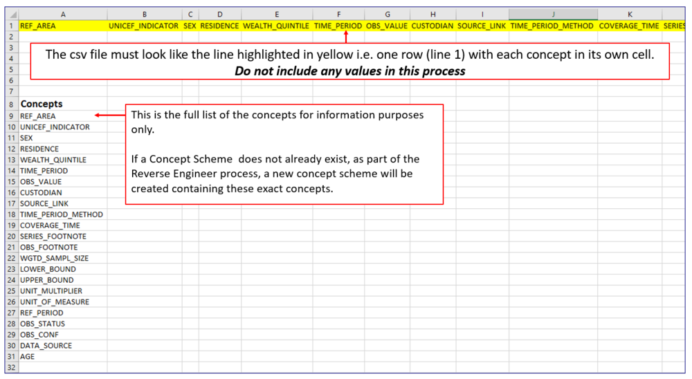
Next, ensure that all unnecessary data is removed and that the individual concepts all appear in the top row with each concept in its own cell.
When done, the file should be saved as an Excel CSV file ready to be used in the Reverse Engineer (RE) process.
Concept Schemes
The RE process includes a step where you can link the concepts to an existing Concept Scheme owned by the same Agency as being used in the RE process. Alternatively, you can ignore this feature in which case the Concept scheme will be created for you.
Codelists
If you decide to use the RE process to create a new Concept Scheme, Codelists will also be created for any concepts that you specify thus in Step 2 of the Wizard (see below).
Note that the codelist will be empty.
Using an existing Concept Scheme
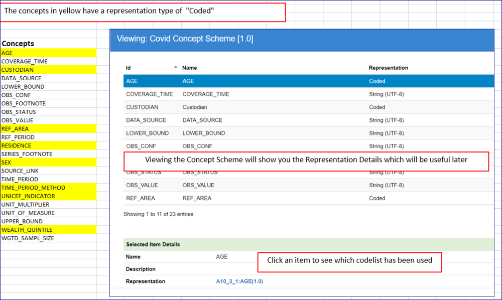
If you are planning to use an existing concept scheme you will need to be aware of how the concept scheme itself has been created.
Process
Reverse Engineer Wizard - Step 1 - High Level Details
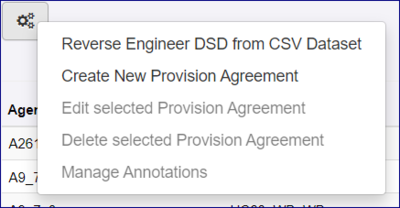
The RE option is available from the Data options, Data Structure, Dataflow and Provision Agreement.
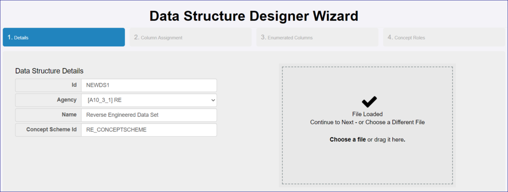
In Step 1 of the Wizard, enter the required ID and Agency together with a suitable name.
If you are using an existing Concept Scheme, it MUST belong to the same Agency and use the same ID. If the Registry does not find an exact match is will create a new concept scheme using the Agency and ID.
If the Concept scheme ID is left blank, the Registry will create a new Concept Scheme.
Next, select your CSV datafile or drag it onto the panel. If successful a tick will appear as shown in the image below.
Click Next to continue.
Reverse Engineer Wizard - Step 2 - Column Assignment
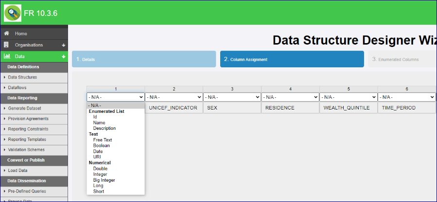
This step allows you to define how each of the columns are to be treated. If you click the down chevron you will see the options available:
Make the appropriate selections for EVERY column as shown in the example below then click Next to continue.
Note that if you select an Enumerated type (Example ID), a codelist will be created.
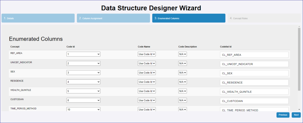
Reverse Engineer Wizard - Step 3 - Enumerated Columns
Step 3 will display the Concepts that in Step 2, you chose (in this example) "Use Code ID". If you are using an existing Concept Scheme, this step is for information purposes only, however if you are creating a Concept Scheme the settings here will determine the Codelists which will be created along with the Concept Scheme.
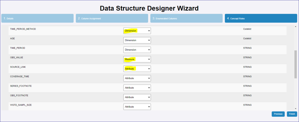
Reverse Engineer Wizard - Step 4 - Concept Roles
This step allow you to define the role for each concept (Dimension, Attribute or Measure) as shown in the example below.
Click Next to continue.
You will be asked to confirm and then you will be taken to the Data Structure page with the newly created DSD highlighted.
Data
To load, validate or convert a data file against this new Data Structure, all you need to do is to add the Data Structure ID etc in accordance with the rules regarding the file format. You can learn more about file formats here.
If you intend to Publish the data you will need to create a Dataflow and a Provision Agreement. You can learn more here.
